Next: Line Detection
Up: Results
Previous: Results
Calibration
To measure the accuracy, the results of calibration (inner and outer geometry) are used to re-project the world coordinate points to image coordinates. In an ideal model, the image points and the re-projected points would perfectly match. Unfortunately, this does not happen.
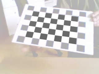 |
Figure 4.1 shows the re-projection using maya. The translation vector and the inverse rotation matrix was used to move and rotate the camera. The intrinsic parameters of the real camera and the camera used for re-projection in MAYA match. Unfortunately, distortion can not be modeled in MAYA, however the calibration pattern fits almost perfectly. The result can be used as a visualization to demonstrate the potentials but cannot be used to measure the accuracy of the calibration. The world coordinates have to be re-projected using a mathematical formulation in which lens distortion is modeled, i.e. the same model as used for calibration. The transformation that projects the world coordinates to image coordinates passes through the following stages.
 | (4.1) |
To calibrate the cameras, at least two images of the calibration pattern are needed. Figure 4.2 shows ten images recorded with the left camera.
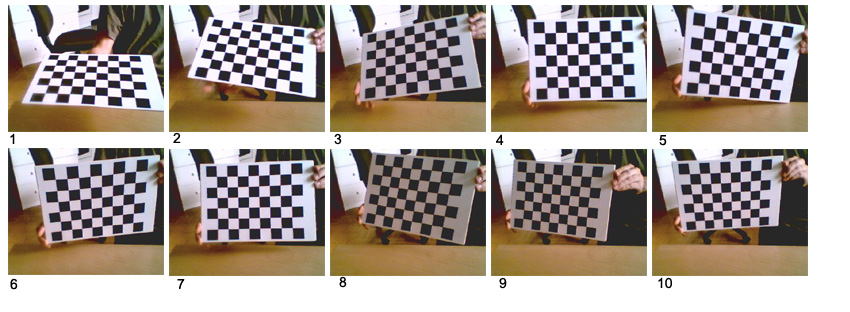 |
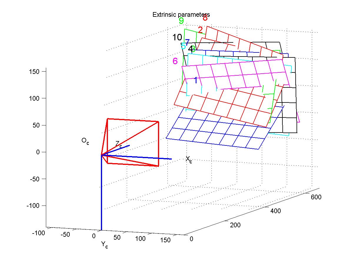
The patterns inside the images have different attitudes and positions in every image. This is needed, otherwise the calibration method would be unable to solve the calibration problem correctly. Once the calibration is done, the attitude of the calibration patterns, and more precisely, the translation and rotation in reference to the camera, is known. Figure 4.3 shows the reconstructed calibration patterns.
We can use this information to re-project the calibration patterns onto the images. Figure 4.4 shows the result of re-projection of the upper left corner for each image. It is a zoomed view to see the deviation. The depicted cut-out has a size of 5x5px. Calculated edge points are marked as circles and re-projected points are marked as crosses.
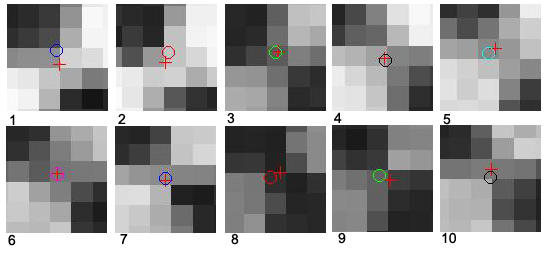
The estimator for the standard deviation of the difference between the original point and the re-projected one is called pixel error. It can be used as an estimation of the accuracy of the re-projection. Table 4.1 shows the re-projection error for every calibration image. It can be seen that the re-projection is very accurate. The calibration works with subpixel accuracy, the mean pixel error is below 0.17 pixels. The mean and median of x and y are very small, and can be further decreased by adding more calibration images.
Figure 4.5 shows the re-projection errors of the 10 calibration images for the left camera. The calibration pattern has 48 internal corners, thus 48 points are plotted in an own color for every image. All deviations from the center are below 0.6 px.
|
Equation 4.2 shows the pixel error in closed form
The quality of the calibration has no influence to the quality of the line detection, which is investigated in the next section, but it has a strong influence on the correspondence analysis and the 3D reconstruction. Because the line detection works on rectified images, which are computed using the fundamental matrix ![]()
![]() and
and ![]() results of the prior calibration. If the rectification does not work properly, the attitudes of the lines are adulterated and thus correspondences may not be established. In addition, the disparity between two lines is also falsified. This has a direct influence to the 3D reconstruction, as well as other inner camera parameters have an influence to the final result (e.g. depth depends on effective focal length
results of the prior calibration. If the rectification does not work properly, the attitudes of the lines are adulterated and thus correspondences may not be established. In addition, the disparity between two lines is also falsified. This has a direct influence to the 3D reconstruction, as well as other inner camera parameters have an influence to the final result (e.g. depth depends on effective focal length ![]() ,
, ![]() and
and ![]() depends on principal point). If the camera coordinates are transformed into world coordinates, the error in the extrinsic camera parameters is reflected in the world coordinates.
depends on principal point). If the camera coordinates are transformed into world coordinates, the error in the extrinsic camera parameters is reflected in the world coordinates.
Next: Line Detection
Up: Results