Next: Summary
Up: Methods
Previous: 3D Reconstruction and Visualization
Robot Head
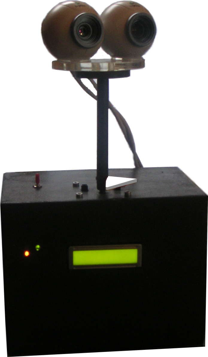
Because the system was built with regard to use it on a mobile robot with a rotating head, a prototype, which can be seen in Figure 3.15, was developed. The electronics and mechanics are inside a wooden box, on which the cameras are mounted. The cameras can be rotated at a maximum of 270![]()
![]() . Two optoelectronic couplers are responsible that the head does not turn in while receiving commands from the server. The MC does all the calculations needed, except the image processing, which is done on the controlling computer. It is also responsible to guide the head.
. Two optoelectronic couplers are responsible that the head does not turn in while receiving commands from the server. The MC does all the calculations needed, except the image processing, which is done on the controlling computer. It is also responsible to guide the head.
According to Figure 3.1 at the beginning of this chapter, the LM would be concerned with this assignment (e.g. move forward and rotate the head clockwise in order to find the ball, that just moved out of the field of view). The controller as a standalone machine is not very intelligent because it is not able to process the images yet. Also the connection between the head and the server is wired, which is a big problem when it comes to a mobile robot which is capable of moving around. This will be the major concern in my future work.
 |
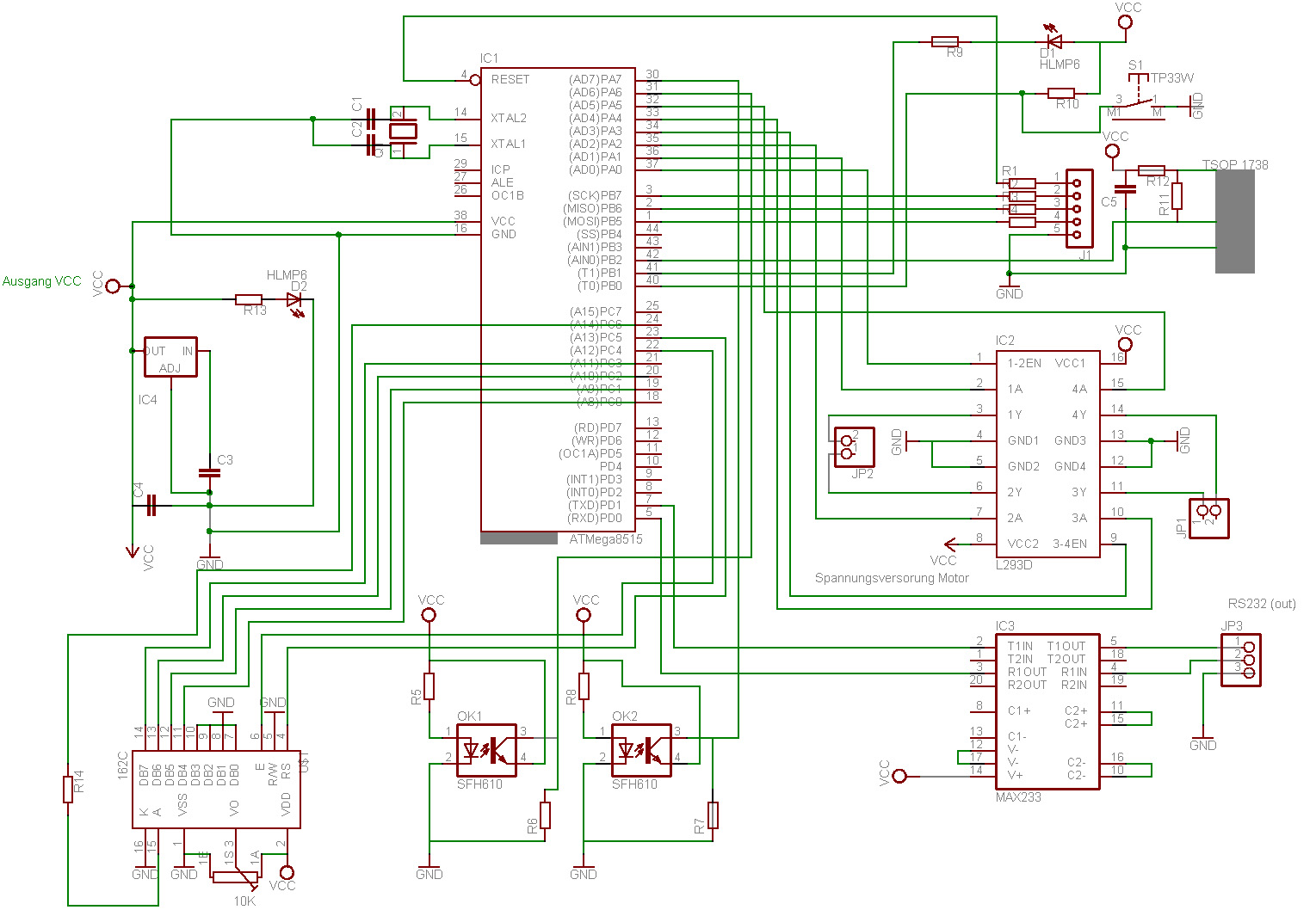
The wire diagram of the robot-head is shown in Figure 3.16. The main parts of the diagram are
- The voltage regulator
- is responsible to transform the input voltage to constant

 . The two capacitors suppress possible oscillations. The rotating head can be used within the range from to
  . If a higher voltage is used, the system still works, but the regulator will become very hot and thus a lot of energy is lost.
 - The tuned circuit
- generates a

 frequency, which is used as an external clock generator. Although there is an internal clock generator, the external is used because the other only oscillates with 1
 .The main part of this circuit is a crystal.
 - The RS232 interface
- is responsible for the communication between the robot and the computer and vice versa. The Max233 chip does the conversion from
![$ [0,5]V$](https://www.anagram.at/app/uploads/2014/02/img260.png)
![$ [0,5]V$](data:image/svg+xml,%3Csvg%20xmlns=%22http://www.w3.org/2000/svg%22%20viewBox=%220%200%2057%2037%22%3E%3C/svg%3E) to
to ![$ [-9,+9]V$](data:image/svg+xml,%3Csvg%20xmlns=%22http://www.w3.org/2000/svg%22%20viewBox=%220%200%2086%2037%22%3E%3C/svg%3E) . Three pins of the serial interface of the computer are used: RxD,Txd and GND.
. Three pins of the serial interface of the computer are used: RxD,Txd and GND. - The motor controller
- is able to trigger two DC-motors. So far only one is connected, but it would be able to trigger two motors. The input voltage of the whole circuit3.6 is used as current supply of the motor. So far software PWM (Pulse Width Modulation) is used to trigger the motors, but it is planned to use hardware PWM.
- The parallel interface
- is where the controller can be programmed. I use the avr-gcc compiler to generate programs that can be run on the microcontroller.
- The LCD display
- is used to communicate with the user and connected to pins 0 to 5 at port E. It uses 4-Bit mode to transfer the data.