• Skip to primary navigation
  • Skip to main content
  • Skip to footer
  • Welcome to the world of Anagram Engineering
  • Who we are
  • Leistungen
    • Web Development
    • Embedded Systems
  • References
    • Customers
    • Webdesign & Webapps
    • Mobile Apps
    • Embedded Systems
    • Cloud Apps
  • News

Search

Anagram Engineering

Webdesign und Softwarelösungen aus Vorarlberg. Ihr Partner für innovative Lösungen rund ums Internet. Full Service Agentur.

Calibration


Next: Edge detection
Up: Methods
Previous: Image Acquisition


Calibration

To gain information about the internal and external camera geometry, as well as the geometric relation between both cameras, the algorithm proposed by Zhengyou Zhang, which is described in [Zha00], was used. In order to calibrate the cameras, the calibration routine needs at least two observations of a planar pattern with different orientations. The OpenCV implementation uses a chessboard-pattern, as shown in Figure 3.4.

Figure 3.4:
Calibration pattern used by the OpenCV calibration method
Image chessboardpattern

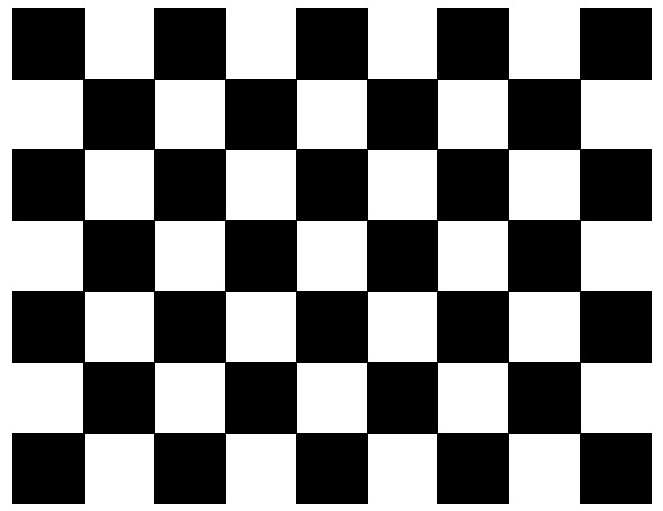
The benefit of this calibration technique is its simplicity, flexibility, robustness, low cost and of course it is already implemented. To calibrate a stereo system using this technique, it is only needed to define the number of internal corners, the size of the squares in mm and the number of views to be taken into account. For example, the calibration pattern shown in Figure 3.4 contains 8 x 6 internal corners and when printed on a A4 paper the squares are 18mm x 18mm. For the calculation, ten different views of the calibration pattern, which has to be visible in both images, e.g. in the left and right view, are used. The first step of the implementation is to locate internal chessboard corners. For example, a simple chessboard has 8 x 8 squares and 7 x 7 internal corners, that is, points, where the squares are tangent. Initially the corners are approximated and if a corner is found, it is highlighted inside the image. The two images at the bottom of Figure 3.5 shows the result of this process.

Figure 3.5:
Highlighting of the images during calibration
Image calibration

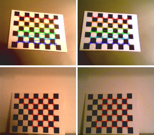
If all corners of the chessboard pattern have been found, the highlight changes it is color and connects the single corners. The two images at the top of Figure 3.5 depicts this situation. In this stage the algorithm tries to find the corners using subpixel accuracy [Res01]. If the pattern is found in both images, the coordinates of the corner candidates are stored for the succeeding calculation. If enough patterns have been found, the algorithm computes the intrinsic and extrinsic camera parameters. First it starts with an analytical solution which is followed by a non-linear optimization technique based on the maximum likelihood criterion3.4. The resulting calibration file is shown in Table 3.1, where

Table 3.1:
Results of calibration for both cameras

Results of calibration for the left camera

493.774 0 196.450
camera matrix 0.000 496.007 128.258
0.000 0.000 1.000
0.005 -1.000 0.011
rotation matrix 1.000 0,005 -0.028
0.028 0.011 1.000

translation vector
88.17 -79.706 611.79

distortion

0.738 -1.494 -0.03 0.024

Results of calibration for the right camera

497.525 0.000 172.205

camera matrix
0.000 500.180 128.569

0.000 0.000 1.000
0.034 -0.999 -0.009

rotation matrix
0.997 0.034 -0.063

0.063 -0.007 0.998

translation vector

141.617 -91.735 617.539

distortion

0.668 -3.175 -0.004 0.022

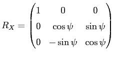
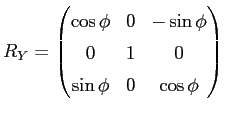
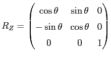
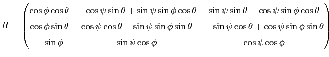
the first two diagonal elements of the camera matrix are the effective focal lengths in x and y direction given in pixels. The third and sixth value are the camera center coordinates, also in pixels. The translation vector is given in mm and describes the translation between the camera and the world coordinate system. The rotation matrix specifies the rotation between the camera and the world coordinate system and is defined as the composition of rotations (roll $ psi$, pitch $ phi$, yaw $ theta$) around the X, Y and Z axis.

$displaystyle R = R_X cdot R_Y cdot R_Z$ (3.1)


Matrix $ R_X$ describes the rotation around the X axis and is defined as

$displaystyle R_X = begin{pmatrix}1 & 0 & 0  0 & cospsi & sinpsi  0 & -sinpsi & cospsi end{pmatrix}$ (3.2)


Matrix $ R_Y$ describes the rotation around the Y axis and is defined as

$displaystyle R_Y = begin{pmatrix}cosphi & 0 & -sinphi  0 & 1 & 0  sinphi & 0 & cosphi end{pmatrix}$ (3.3)


Matrix $ R_Z$ describes the rotation around the Z axis and is defined as

$displaystyle R_Z = begin{pmatrix}costheta & sintheta & 0  -sintheta & costheta & 0  0 & 0 & 1 end{pmatrix}$ (3.4)


Equation 3.1 combines the three matrices $ R_X$,$ R_Y$ and $ R_Z$, thus $ R$ can be written as

$displaystyle R = begin{pmatrix}cosphi costheta & -cospsi sintheta + ...
... theta  -sin phi & sin psi cos phi & cos psi cos phi end{pmatrix}$ (3.5)


As one can see, after calibration, the relation between the camera and world coordinate system is completely described. Many different methods for camera calibration have been proposed so far. [CF97] is a paper on the historical development of camera calibration techniques, which also covers an exhaustive literature survey.

After the images are transferred to memory, the result of the calibration is used to rectify the images. The benefit is that corresponding elements can be found on the horizontal scan line. Before the process of rectification, also a point to line correspondence could be established, but the epipolar line has to be taken into consideration. After rectification there is no further need to think about the epipolar geometry.


Next: Edge detection
Up: Methods

Footer

Contact US

Stiegstrasse 24
6830 Rankweil

+43 650 925 62 64

About US

Anagram Engineering develops software for Web, Mobile, Tablet and embedded devices.

Learn More

© 2025 · Anagram Engineering

  • terms & conditions
  • impress
  • customers
  • References
  • who we are
Manage Cookie Consent
Wir benützen Cookies um unsere Website und unsere Services zu optimieren.
Funktional Always active
The technical storage or access is strictly necessary for the legitimate purpose of enabling the use of a specific service explicitly requested by the subscriber or user, or for the sole purpose of carrying out the transmission of a communication over an electronic communications network.
Preferences
The technical storage or access is necessary for the legitimate purpose of storing preferences that are not requested by the subscriber or user.
Statistik
The technical storage or access that is used exclusively for statistical purposes. The technical storage or access that is used exclusively for anonymous statistical purposes. Without a subpoena, voluntary compliance on the part of your Internet Service Provider, or additional records from a third party, information stored or retrieved for this purpose alone cannot usually be used to identify you.
Marketing
The technical storage or access is required to create user profiles to send advertising, or to track the user on a website or across several websites for similar marketing purposes.
Manage options Manage services Manage vendors Read more about these purposes
Einstellungen
{title} {title} {title}
  • Deutsch
  • English